This manual covers the following parts of Dilay:
Installing
In order to run Dilay, you need a graphics card that supports OpenGL 2.1 (for wireframe rendering the GL_EXT_geometry_shader4 OpenGL extension must be supported).
Windows
Pre-built installer for Windows is provided in the Download section.
Linux
Pre-built AppImage for Linux is provided in the Download section.
From Source
Building from source requires the following tools:
Firstly, get Dilay’s sources from GitHub:
$ git clone https://github.com/abau/dilay.git
$ cd dilay
Building is done via:
$ qmake -r PREFIX=DIR
$ make release
If GLM is not installed in one of your systems standard directories, add the argument
INCLUDEPATH += GLM_DIRto qmake with GLM_DIR denoting the path where GLM is installed. Add the -jN argument to make for building using N parallel processes. Install by running:
# make installIf no PREFIX was given to qmake, Dilay is installed to /usr/local/.
Graphical User Interface
Dilay’s main window consists of several parts: the 3D view in the center, the toolbar on the left, the infobar on the right, and the the menubar at the top.
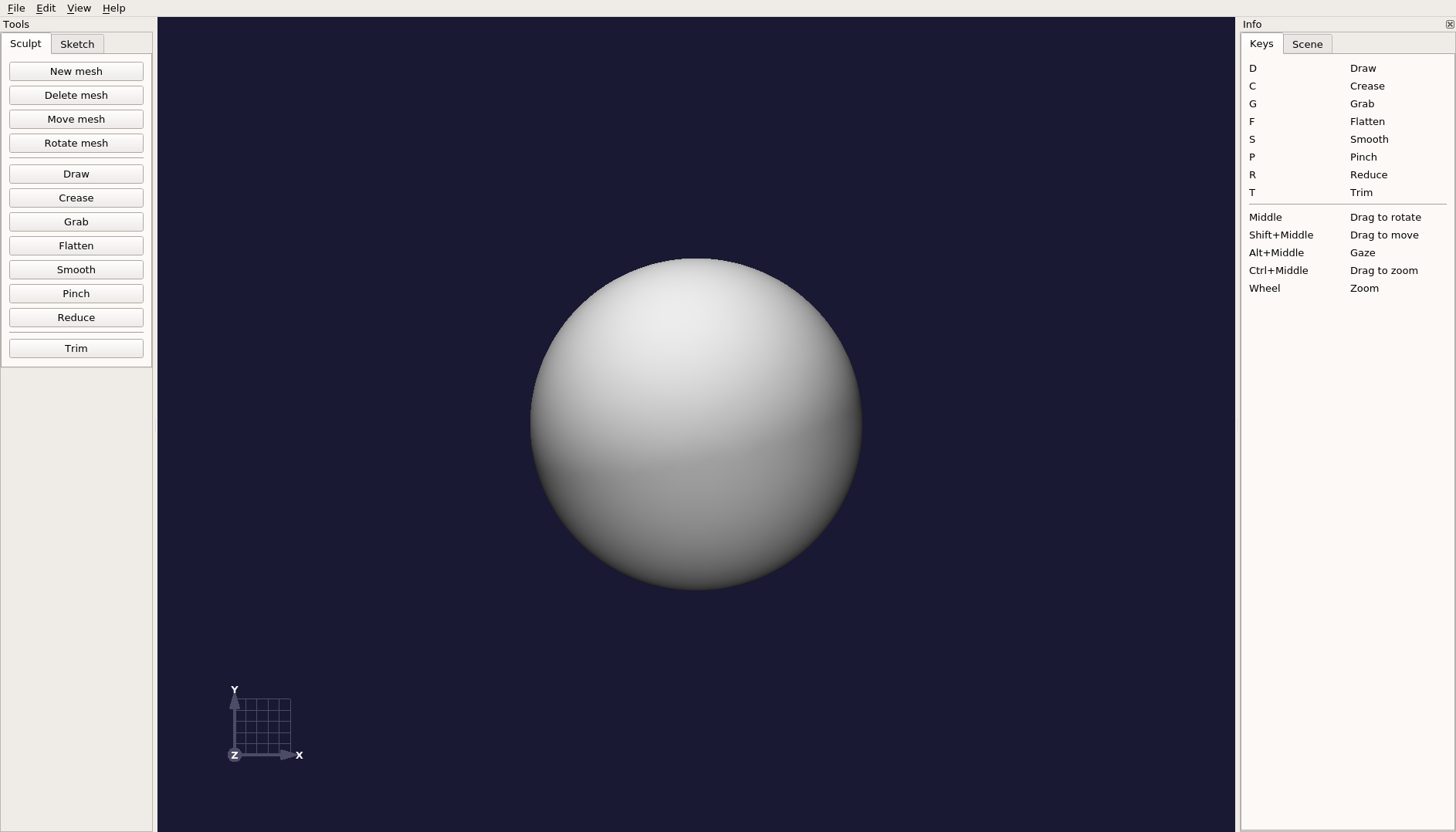
3D View
The 3D view covers most of Dilay’s main window. It shows the mesh that is currently being sculpted and the 3D coordinate system along with the current primary plane. The primary plane denotes the plane (XY, YZ, or XZ) which faces towards the virtual camera. Note that the primary plane changes when rotating around the gaze point.
The 3D view can be manipulated via the items in the view menu and features a context menu when right-clicking on a mesh.
Context Menu
A context menu can be activated by right-clicking on a mesh in the 3D view or the Scene section of the infobar.
When right-clicking on a mesh, the following operations are available:
Copy mesh copies the selected mesh.
Mirror mesh mirrors the selected mesh on the YZ-plane.
Move mesh to center moves the selected mesh’s center to the origin of the present scene.
Normalize mesh scaling scales the selected mesh to an optimal size for sculpting.
Delete mesh deletes the selected mesh.
When right-clicking on a sketch, the following operations are available:
Copy sketch copies the selected sketch.
Delete sketch deletes the selected sketch.
Toolbar
The tools that are provided by Dilay are located in the toolbar on the left of the screen. There are two different set of tools: one for sculpting meshes and one for sketching meshes.
Mesh Sculpting
In the following, we look at the tools for sculpting meshes in Dilay.
New mesh generates a new mesh at the origin of the present scene. The number of subdivisions is configurable in the toolbar.
Delete mesh deletes a mesh.
Transform mesh either
- moves a mesh along the camera plane or the primary plane; or
- rotates a mesh around the mouse intersection point, the mesh’s center, or the scene’s origin.
The sculpting tools provided by Dilay change the geometry of the current mesh in one way or another. All these tools share some common parameters:
Radius: The radius determines the range that is affected by a tool. It is visualized by the size of the red cursor in the 3D view. The radius also determines the level of detail that is added by the sculpting tools when locally subdividing the mesh.
Absolute radius: The Absolute-radius checkbox switches between the absolute-radius and relative-radius mode. In the absolute-radius mode, the radius of the sculpting tools does not depend on the distance of the virtual camera to the mesh, i.e., when zooming, the radius does not change. Consequently, it does not make a difference whether you sculpt the mesh from close-up or from distance. In the relative-radius mode, the radius of the sculpting tools depends on the distance of the camera to the the mesh, i.e., when zooming, the radius changes accordingly.
Subdivide: The Subdivide checkbox determines whether a sculpting tool should locally subdivide the mesh whenever more details are needed. By default, subdivision is enabled. Note that the Reduce tool is not affected by this checkbox.
Mirror: When this checkbox is enabled, all sculpting actions on the present mesh are mirrored at the YZ-plane. The intersection of the YZ-plane and the current mesh is highlighted by a gray line. For technical reasons, mirroring does not produce a perfectly symmetric mesh. However, pressing the Sync button synchronizes both sides of the YZ-plane: all vertices of the mesh that lie on the positive side of that plane in regard to the X axis are mirrored.
Dilay provides the following sculpting tools:
Draw: The Draw tool smoothly sculpts the mesh. Its strength is given by the Intensity parameter. Activating the Invert checkbox inverts the sculpting direction, so that the tool creates a hollow at the cursor position. Activating the Flat checkbox results in a more leveled deformation. Activating both the Constant height and Flat checkboxes prevent deformations to add up when dragging over the same spot multiple times in a single stroke.
Crease: The Crease tool creates a more narrow deformation. Intensity and Invert parameters have identical meanings as for the Carve tool.
Grab: The Grab tool allows to grab and move vertices of the mesh. This is useful for moving large parts of a mesh (large radius) or creating short spikes (small radius). Optionally, the movement can take place along the current primary plane by activating the corresponding checkbox. The Grab tool can be configured to discard backfaces, i.e., faces on the opposite side of the mesh. This is useful when this tool is applied to thin meshes.
Flatten: The Flatten tool generates a flat area by leveling all detailed structures. Its strength is given by the Intensity parameter. By activating the Lock plane options, all vertices are being projected onto the same plane which is determined by the initial mouse click.
Smooth: The Smooth tool smoothes detailed structures by averaging over all vertices that are affected by the tool. Its strength is given by the Intensity parameter. By activating the Relax-only option, the effect is more subtle as each vertex will only be affected by its direct neighbors.
Pinch: The Pinch tool moves all affected vertices towards the center of the cursor. This is useful for creating hard edges. By activating the Invert parameter, the vertices are moved away from the center of the cursor.
Reduce: The Reduce tool collapses faces smaller than a certain threshold. This threshold is defined by the Intensity parameter. The effect is best viewed when wireframe rendering is enabled.
Remesh: The Remesh tool either remeshes a single mesh (in Normal mode) or applies one of the Boolean operators Union, Difference, or Intersection by dragging over two meshes.
Trim: The Trim tool either trims parts of mesh, cuts through a mesh, or cuts a slice out of the mesh. The width of the slice or cut is determined by the Width slider.
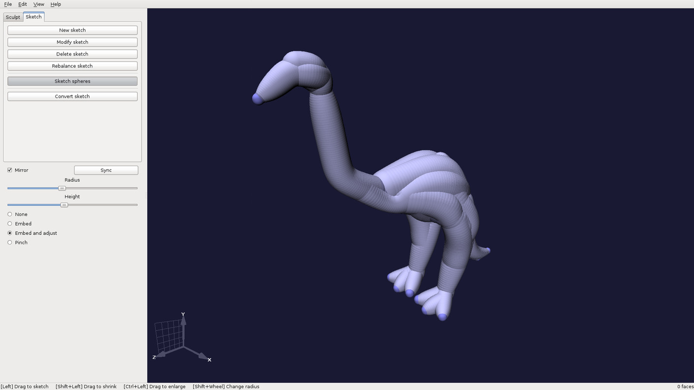
Sketching
Using the tools in the Sketch section of the toolbar allows to sketch a first draft of a mesh. A sketch is a tree-shaped frame of nodes, where each node may have an arbitrary set of child nodes (Example). The first sketched node is denoted as the root of the sketch. The relation between the nodes of a sketch can be inspected by activating wireframe rendering. A sketch can be refined by drafting paths of spheres onto its surface (Example).
The following sketch-related tools are available in Dilay:
Edit sketch either
- generates new sketches; or
- moves, scales, or rotates nodes; or
- generates new nodes.
If the Mirror checkbox is activated, all modifications are mirrored at the YZ-plane intersecting the root node. Pressing the Sync button synchronizes both sides of that YZ-plane: all nodes that lie on the positive side of that plane in regard to the X axis are mirrored.
If the Transform children checkbox is activated, all modifications are applied to the child nodes as well.
If the Split and join checkbox is activated, nodes are nodes are being split from sketches and can be joined to other sketches.
If the Snap checkbox is activated, nodes are snapped to the YZ-plane; the maximum distance of snappable nodes can be adjusted via the Snap width slider.
Delete sketch deletes sketches, nodes, and spheres.
Sketch spheres adds paths of spheres to the surface of a sketch. The Radius parameter determines the size of the spheres, and the Height parameter determines the position of the spheres in relation to the sketch surface. The Mirror checkbox has an identical meaning as for the Modify-sketch tool.
Existing spheres can be smoothed using four different modes of smoothing:
None merely smoothes the path of spheres.
Embed smoothes the path of spheres and embeds the spheres near the endpoints of the path into the sketch.
Embed and adjust resembles the Embed mode but additionally adjusts the spheres’ radii near the endpoints of the path so that they converge to the radii of the spheres that the endpoints are embedded in.
Pinch resembles the Embed-and-adjust mode but pinches the spheres’ radii near the endpoints of the path. This is useful for creating muscle-shaped sketches.
Convert sketch converts a sketch to a sculptable mesh. The Resolution parameter determines the number of vertices in the resulting mesh. Note that the conversion may take a while for high resolutions. If the Move to center checkbox is activated, the mesh is centered at the origin of coordinate system after the conversion.
Infobar
The infobar on the right of the screen shows different context-sensitive information:
The Keys section shows currently applicable shortcuts for various functions.
The Scene section shows the number of faces and vertices for all meshes and sketches in the present scene. A context menu can be activated by right-clicking on a mesh or sketch.
Menubar
The menubar contains the following items:
File:
Open…: Opens a OBJ-file and loads the contained mesh. Dilay asks whether the loaded mesh should be added to the existent scene or replace it.
Save as…/Save: Saves the current mesh in a OBJ file.
Quit: Quits Dilay.
Edit:
Undo: Undoes the last action that changed the mesh.
Redo: Reverts the last Undo action.
Configuration: Opens the configuration dialog.
View:
Toggle info pane: Shows or hides the infopane on the right-hand side of the screen.
Snap camera: Snaps the virtual camera to the closest standard axis. If the camera has already been snapped, it is cyclically snapped to the other standard axes.
Reset gaze point: Resets the gaze point of the virtual camera to the the origin of the 3D coordinate system.
Toggle wireframe: Toggles wireframe rendering. Wireframe rendering of meshes is only available on graphic cards that support the
GL_EXT_geometry_shader4OpenGL extension.Toggle shading: Toggles between smooth and flat shading.
Show floor plane: Toggles rendering of the floor-plane.